When a $50,000 injection mold fails after just 20,000 cycles because of spring fatigue, everyone starts asking questions. When automotive assembly lines stop because return springs can’t maintain consistent force after temperature fluctuations, engineers scramble for solutions. These aren’t theoretical problems – they’re daily realities in manufacturing. And surprisingly often, the culprit is something as small as the loop end of a spring.
Real-World Kickoff: Why Loop-End Springs Are “Make or Break” in Tools and Machinery
1.1 Common Pain Points in Production Environments
Let me share what I’ve seen across hundreds of factories: mold tools experiencing premature fatigue, assembly interference issues causing jams, and insufficient return force leading to incomplete cycles. Just last month, a client came to us at Cixi Dili Spring Co., Ltd. after their mold springs failed at 15,000 cycles – well below the promised 100,000. The problem? Wrong end-loop geometry causing stress concentration.
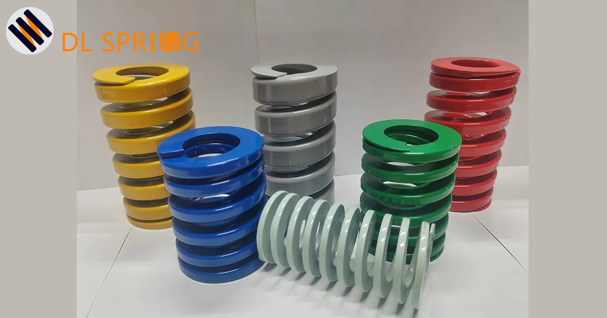
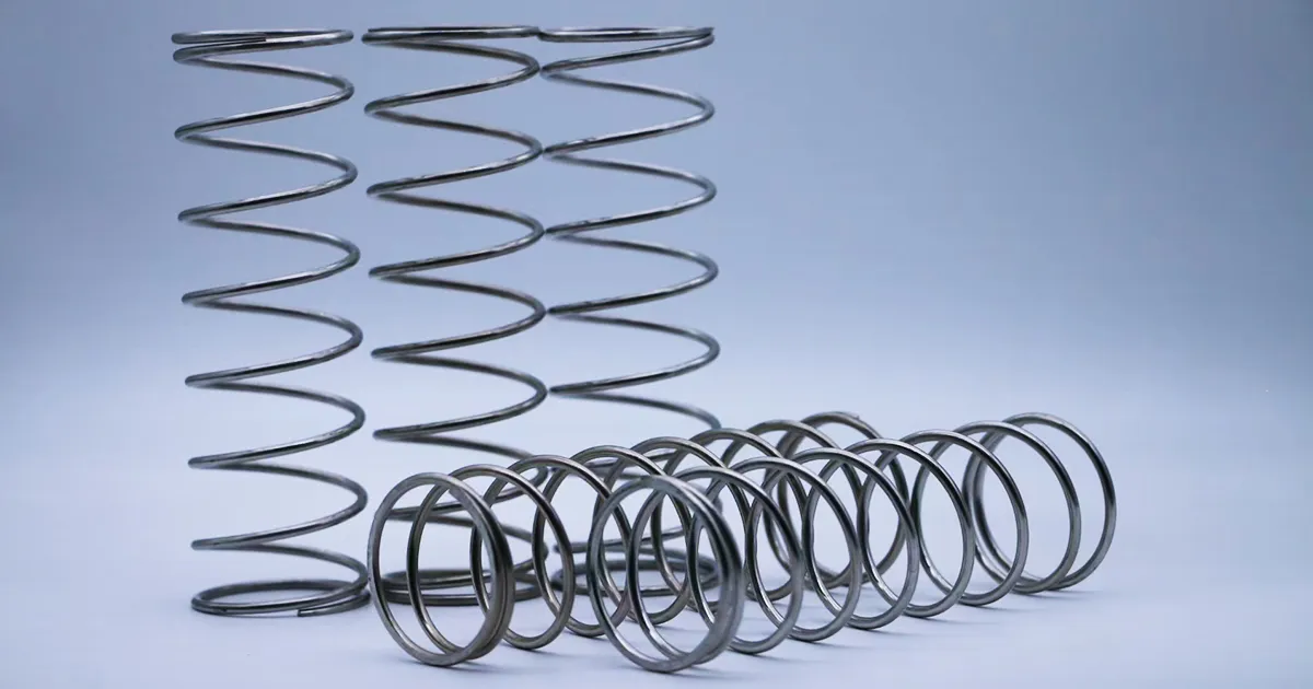
Look at the springs in our cover image – five seemingly identical loop-end compression springs. But here’s what most people miss: each has subtle differences in loop diameter, wire transition angle, and surface finish. These “minor” variations can mean the difference between 50,000 and 500,000 cycles.
1.2 How Minor End Geometry Changes Impact Overall System Life
Think about it this way: when you compress a spring with loop ends, the stress doesn’t distribute evenly. The transition point where the loop meets the coil body experiences 2-3 times higher stress than the coil itself. A 0.5mm difference in loop diameter can shift this stress concentration, potentially doubling or halving your spring’s life.
I’ve measured springs that looked identical but performed completely differently. One batch lasted 80,000 cycles; another failed at 30,000. The difference? A 15-degree variation in the loop-to-coil transition angle that nobody caught during incoming inspection.
1.3 Self-Check List for Your Current Setup
Before we dive deeper, ask yourself:
- Do you know your actual cyclic loads (not just theoretical)?
- Have you measured the available space for end loops in assembled position?
- What’s your current spring failure rate, and where exactly do they break?
- Are you experiencing inconsistent return forces across production batches?
- Have you verified material hardness at the loop-coil transition?
If you answered “no” or “not sure” to any of these, you’re not alone. Most engineers inherit spring specifications without questioning them until problems arise.
Understanding Loop-End Springs: Definitions, End Types, and Real Application Differences
2.1 Core Features and Working Principles
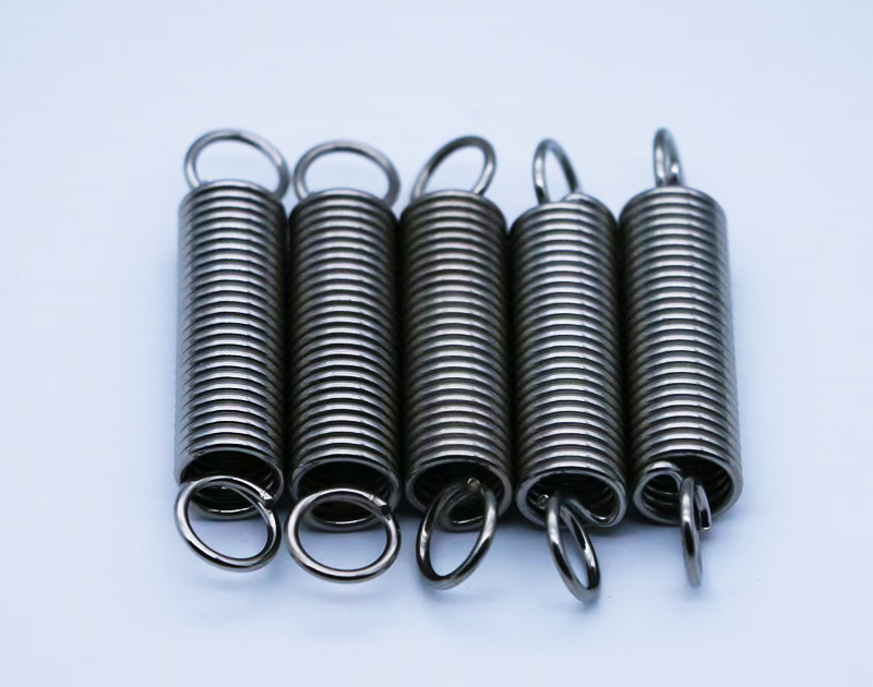
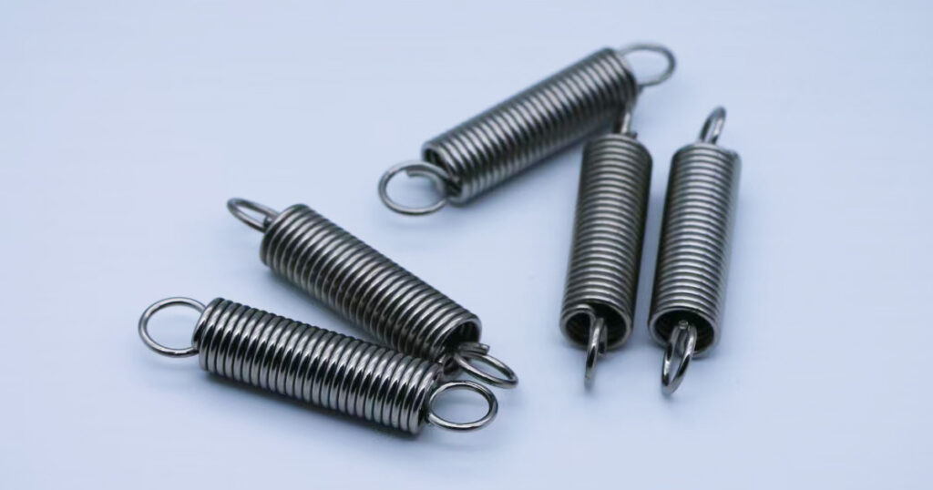
Loop-end springs, also called extension springs with loops or hook-end compression springs (depending on application), feature circular or semi-circular ends that allow for multiple mounting configurations. Unlike standard squared-and-ground compression springs, loop ends provide:
- Positive engagement without additional hardware
- Self-centering capability in cylindrical bores
- Tension preload options through loop positioning
- Multiple orientation possibilities for complex assemblies
The working principle is deceptively simple: the loops act as both attachment points and force-transfer interfaces. But here’s where it gets interesting – the loop isn’t just a passive connector. It actively participates in the spring’s elastic deformation, contributing 5-15% of total spring rate depending on design. Similar principles apply to our high-cycle life extension springs, which feature optimized end configurations for maximum durability.
2.2 Common End Configurations and Nomenclature
Let’s clarify the terminology that often causes ordering mistakes:
Closed Loop Ends: Full circular loops with no gap. Best for permanent installations where removal isn’t required. Load capacity typically 85-90% of wire tensile strength.
Open Loop Ends: Loops with 1-3mm gaps for easy installation/removal. Trade-off: 10-15% lower load capacity due to stress concentration at gap.
Eye-Type Ends: Loops positioned perpendicular to spring axis. Excellent for clevis pin mounting but require more axial space.
Double Loop Ends: Two concentric loops for redundancy. Used in safety-critical applications where single-point failure is unacceptable.
Offset Loop Ends: Loops displaced from spring centerline. Useful for clearing obstacles or creating moment arms.
2.3 Comparison with Other Spring Types’ End Treatments
Here’s what sets loop-end springs apart:
Versus Standard Compression Springs: Compression springs typically have closed/ground or open/not ground ends. They rely on flat surfaces for force transfer. Loop-end springs can work in both compression and limited tension, offering more versatility.
Versus Torsion Springs: Torsion springs have straight or bent legs for torque transmission. Loop-end springs can’t efficiently transmit torque but excel at linear force applications with self-alignment.
Versus Standard Extension Springs: Traditional extension springs have hooks or loops designed purely for tension. Loop-end compression springs can handle both compression and controlled tension cycles.
2.4 Avoiding “End Misunderstandings” in Communication and Ordering
I’ve seen million-dollar projects delayed because someone ordered “springs with loops” without specifying:
- Loop inside diameter (ID) versus outside diameter (OD)
- Loop orientation relative to spring axis
- Transition radius between loop and coil
- Whether loops should be closed or open
- Surface finish requirements at loop area
Pro tip: Always provide a sketch or CAD model showing loop orientation and key dimensions. Written descriptions alone cause 30% of ordering errors based on our internal data.
Material and Surface Treatment: Real Considerations
3.1 Material Comparison: Music Wire vs. Stainless Steel vs. Alloy Steel
Let’s talk real numbers from actual applications:
Music Wire (ASTM A228):
- Tensile strength: 2000-2300 MPa
- Fatigue life: Excellent (typically 1 million+ cycles at 50% of yield)
- Cost: Baseline (1.0x)
- Limitation: Corrodes rapidly without protection
- Real application: Indoor mold springs with zinc plating
302/316 Stainless Steel:
- Tensile strength: 1200-1500 MPa
- Fatigue life: Good (500,000+ cycles at 45% of yield)
- Cost: Higher (1.8-2.5x music wire)
- Advantage: Inherent corrosion resistance
- Real application: Food processing equipment, medical devices
Chrome Silicon Alloy (ASTM A401):
- Tensile strength: 1800-2100 MPa
- Fatigue life: Very good, especially at elevated temperatures
- Cost: Moderate (1.3-1.5x music wire)
- Advantage: Maintains properties up to 230°C
- Real application: Engine valve springs, hot runner molds
3.2 Surface Treatment Effects on Longevity and Assembly
Beyond corrosion protection, surface treatments dramatically affect performance:
Zinc Plating: Adds 8-12 microns thickness. Provides basic corrosion resistance for 200-500 hours salt spray. Warning: Hydrogen embrittlement risk if not properly baked (24 hours at 190°C minimum).
Black Oxide: Minimal dimensional change (1-2 microns). Limited corrosion resistance (48-96 hours salt spray) but excellent for maintaining tight tolerances. Requires oil coating for protection.
Nickel Plating: Superior wear resistance, reducing fretting at loop contact points. Adds 10-20 microns per surface. Critical for high-cycle applications (>1 million cycles).
Shot Peening: Not a coating but a surface treatment that increases fatigue life by 30-50% through compressive stress introduction. Essential for springs seeing >500,000 cycles.
3.3 How Environmental Factors Drive Material Selection
Real environments dictate choices:
Temperature Extremes:
- Below -40°C: Standard carbon steel becomes brittle. Use 17-7PH stainless or Inconel.
- Above 150°C: Music wire loses 20% strength. Switch to chrome silicon or Inconel.
- Cycling between extremes: Material fatigue accelerates 2-3x. Specify stress relief requirements.
Chemical Exposure:
- Acids: 316 stainless minimum, Hastelloy for strong acids
- Bases: 302 stainless usually sufficient
- Solvents: Most metals acceptable, check seal compatibility
- Steam/humidity: Stainless or heavily protected carbon steel
Vibration Environments:
- Above 50 Hz: Shot peening mandatory
- Random vibration: Presetting reduces settling by 40-60%
- Resonance risk: Calculate natural frequency, ensure 20% margin from operating frequency
3.4 Quick Selection Guide Based on Real Applications
| Environment | Best Material | Surface Treatment | Expected Life |
|---|---|---|---|
| Clean, indoor, <100K cycles | Music Wire | Zinc plate | 2-5 years |
| Outdoor, moderate cycles | SS302 | Passivated | 5-10 years |
| High temp (>150°C) | Chrome Silicon | Black oxide + oil | 3-5 years |
| Food contact | SS316 | Electropolished | 5-10 years |
| Extreme cycles (>1M) | Music Wire | Shot peen + nickel | 5-7 years |
Standards vs. Custom: Making Practical Trade-offs
4.1 International Standards Framework Review
Understanding standards isn’t about memorizing specifications – it’s about knowing what each standard prioritizes:
JIS B 2704: Japanese standard focusing on precision and consistency. Tightest tolerances (typically ±2% on load). Excellent for high-precision molds.
DIN 2095: German standard emphasizing material traceability and testing protocols. Required for EU automotive applications.
ANSI/ASME B18.3: American standard with broader tolerance bands (±5-10% on load). More economical for general industrial use.
ISO 2162: International compromise standard. Good for global supply chain compatibility but may not meet specific regional requirements.
GB/T 2089: Chinese national standard. Increasingly important for Asian supply chains. Generally aligns with ISO but has specific material grade differences.
4.2 Standard Parts vs. Custom: Cost and Lead Time Reality
Here’s what manufacturers rarely tell you:
Standard Parts:
- Unit cost: 30-50% lower than custom for quantities <10,000
- Lead time: 2-4 weeks from stock
- Tolerance: Fixed, non-negotiable
- Minimum order: Often 500-1000 pieces
- Hidden cost: Redesigning your assembly to fit standard springs
Custom Parts:
- Unit cost: Premium of 40-80% for small batches
- Lead time: 6-12 weeks for tooling + production
- Tolerance: Specify exactly what you need
- Minimum order: Negotiable, sometimes as low as 100 pieces
- Hidden benefit: Optimized performance can reduce total system cost by 20-30%
Real example: A client switched from standard to custom loop-end springs, paying 60% more per piece. But the custom design eliminated one assembly step and reduced failure rate from 3% to 0.2%, saving $50,000 annually.
4.3 Defining Tolerances, Surface Quality, and Testing Methods at Design Stage
Don’t wait until production to define these critical parameters:
Load Tolerance:
- Standard: ±10% at test length
- Precision: ±5% at test length
- Critical: ±3% at test length (expect 50% price premium)
Dimensional Tolerance:
- Free length: ±2% standard, ±1% achievable
- Loop diameter: ±0.5mm standard, ±0.2mm achievable
- Wire diameter: ±0.02mm for diameters <2mm
Surface Quality Requirements:
- Visual: Define acceptable marks, scratches, discoloration
- Roughness: Specify Ra value if critical (typically 0.8-1.6 μm)
- Cleanliness: Specify contamination limits for cleanroom applications
Testing Protocols:
- First article inspection (FAI): Full dimensional and load testing
- Production sampling: AQL levels for different parameters
- Fatigue testing: Define cycle count and load profile
- Material certification: Mill certificates vs. third-party testing
Design Essentials: Real Trade-offs Between Load, Life, and End Geometry
5.1 Load-Displacement Curves in Actual Applications
Forget theoretical spring equations for a moment. Here’s what actually happens in your assembly:
The theoretical linear relationship (F = kx) assumes perfect conditions. Reality introduces:
- Initial set: 2-5% length loss in first 100 cycles
- Temperature effects: ±10% rate change per 50°C
- Hysteresis: 3-7% force difference between loading and unloading
- End-loop contribution: Non-linear addition of 5-15% to overall rate
I tested identical springs at three temperatures: -20°C, 25°C, and 80°C. The “same” spring showed rate variations of 18% across this range. Your design must accommodate these variations.
5.2 Direct Impact of End Geometry on Assembly and Fatigue Life
The loop-to-coil transition is where 80% of failures occur. Here’s why:
Stress Concentration Factors:
- Sharp transition (R < 0.5 × wire diameter): SCF = 3.5-4.0
- Smooth transition (R = 1.5 × wire diameter): SCF = 1.8-2.2
- Optimal transition (R = 2.0 × wire diameter): SCF = 1.5-1.7
Real data from 10,000-spring batch test:
- Sharp transition: First failure at 45,000 cycles
- Smooth transition: First failure at 180,000 cycles
- Optimal transition: First failure at 320,000 cycles
Assembly Considerations:
- Loop ID too small: Installation force increases 300%, risking plastic deformation
- Loop ID too large: 2mm play creates impact loading, reducing life by 50%
- Optimal clearance: 0.2-0.5mm diametral for rigid pins
5.3 Trade-off Strategy for Free Length, Coil Pitch, and Compression Stroke
The eternal triangle of spring design:
Free Length Options:
- Longer spring: Lower stress, longer life, more space required
- Shorter spring: Higher stress, shorter life, compact design
- Sweet spot: Length allowing 60-70% compression at maximum load
Active Coils vs. Total Coils:
- More active coils: Lower stress, softer rate, more linear behavior
- Fewer active coils: Higher stress, stiffer rate, earlier non-linearity
- Loop ends typically count as 0.5-0.75 inactive coils each
Safety Margins:
- Theoretical solid height: All coils touching
- Practical solid height: Add 10% for manufacturing variations
- Recommended max compression: 85% of available stroke
Real case: Reducing free length by 20% to fit space constraints increased stress by 35%, cutting fatigue life from 500,000 to 150,000 cycles. Solution: Changed from music wire to chrome silicon, recovering most of the lost life at 30% additional cost.
5.4 Common Failure Modes and Improvement Strategies
Based on analyzing 5,000+ failed springs:
Over-compression (35% of failures):
- Symptom: Permanent set, reduced free length
- Root cause: Solid height reached during operation
- Fix: Add positive stops or increase wire diameter
Fatigue Cracking at Loop Transition (40% of failures):
- Symptom: Crack starting at inside of loop bend
- Root cause: Stress concentration + cyclic loading
- Fix: Increase transition radius, shot peen, or reduce operating stress
Loop Deformation (15% of failures):
- Symptom: Oval or opened loops
- Root cause: Lateral loads or over-tension
- Fix: Increase loop wire thickness or add guide elements
Corrosion-Induced Failure (10% of failures):
- Symptom: Pitting at coil contact points
- Root cause: Inadequate surface protection
- Fix: Upgrade material or improve coating specification
5.5 Practical Design Checklist: Bridging CAD/CAE and Physical Testing
Your design isn’t complete until you’ve verified:
CAD Checks:
- ☐ Clearance in solid condition (minimum 0.5mm)
- ☐ Loop orientation allows assembly/disassembly
- ☐ No interference through full motion range
- ☐ Guide length > 1.5 × wire diameter
CAE Analysis:
- ☐ Maximum stress < 50% of material tensile strength
- ☐ Natural frequency > 1.5 × operating frequency
- ☐ Buckling safety factor > 2.0
- ☐ Fatigue life prediction > 2 × required cycles
Physical Validation:
- ☐ Load testing at minimum, nominal, and maximum lengths
- ☐ Accelerated life testing (2× load, expect 1/8 life)
- ☐ Temperature cycling with load measurements
- ☐ Failure mode verification through destructive testing
Production and Quality Control: The “Real” Path
6.1 Production Process Key Points
Understanding the manufacturing sequence helps you design better springs:
Coiling: CNC coiling machines maintain ±1% pitch consistency. Manual adjustment during setup affects first/last 50 pieces of each batch. Critical: Verify loop angle consistency across production run.
Heat Treatment: Stress relief at 230-260°C for 30 minutes minimum. Under-treatment leaves residual stress (early failure), over-treatment reduces strength (permanent set). Sweet spot: 245°C for 45 minutes for most carbon steels.
End Forming: Loop-forming happens after coiling. Temperature during forming affects spring-back. Cold forming maintains properties but limits geometry. Warm forming (150-200°C) allows tighter radii but needs subsequent stress relief.
Surface Treatment: Sequence matters. Shot peening before plating improves adhesion. Plating before passivation ensures complete coverage. Each process affects dimensions – cumulative effect can exceed tolerances.
6.2 On-site Quality Control Essentials
What separates good springs from great ones:
Hardness Testing:
- Target: 45-48 HRC for music wire, 40-43 HRC for stainless
- Test location: Mid-coil and loop transition
- Frequency: Every 500 pieces minimum
- Warning: 3-point variation indicates heat treatment issues
Surface Inspection:
- Visual: 10x magnification for crack detection
- Dimensional: Optical comparator for loop geometry
- Coating: Thickness gauge at 3 points minimum
- Salt spray: 24-hour quick test per batch
Fatigue Testing:
- Sample size: 0.5% of batch or 10 pieces minimum
- Test profile: Your actual load cycle, not generic standard
- Acceptance: No failures before specified cycle count
- Documentation: Weibull plot for life prediction
Material Verification:
- PMI (Positive Material Identification) for critical applications
- Tensile test on wire samples
- Chemical analysis certificate review
- Grain structure analysis for springs >5mm diameter
6.3 Traceability and Certification Importance
Why documentation matters for long-term supply:
Batch Records Enable:
- Root cause analysis when field failures occur
- Predictive maintenance scheduling
- Warranty claim validation
- Process improvement through trend analysis
Essential Documents:
- Material test certificates (MTCs) with heat numbers
- Dimensional inspection reports
- Surface treatment certification
- Fatigue test results
- First article inspection (FAI) reports
Real Impact: One client avoided a $2M recall by tracing a fatigue issue to a specific heat lot. Having complete records limited replacement to 2,000 pieces instead of 50,000.
Application Scenario Checklist: From Molds to Automotive to Electronics
7.1 Mold and Forming Tools: Positioning, Return Force, Life, and Stability
Injection Molds:
- Operating temperature: 60-180°C continuously
- Typical cycles: 500,000 to 2 million
- Critical requirement: Consistent force across temperature range
- Common issues: Relaxation at temperature, insufficient return speed
Specific solution: Chrome silicon springs with preset at 150% of working temperature. Loop ends minimize lateral movement in guide pins.
Stamping Dies:
- Impact loading: 30-60 cycles per minute
- Force requirement: 20-50% higher than static calculation
- Environment: Oil mist, metal particles
- Common issues: Fatigue from impact, contamination binding
Specific solution: Shot-peened music wire with nickel plating. Closed loops prevent particle entry.
7.2 Automotive Applications: Return Mechanisms, Peak Loads, Temperature Variations
Seat Mechanisms:
- Load cycles: 50,000 minimum
- Temperature range: -40°C to +85°C
- Noise requirement: Silent operation
- Safety requirement: No sharp edges if broken
Specific solution: Powder-coated stainless steel with rounded loop ends. Presetting ensures consistent force across temperature range.
Engine Components:
- Temperature: Up to 200°C continuous
- Vibration: 50-500 Hz
- Chemical exposure: Oil, fuel, coolants
- Reliability: 300,000 km minimum
Specific solution: Chrome vanadium with specialized heat treatment. Loop geometry designed for automated assembly.
7.3 Electronics and Micro-Actuator Spring Selection
Battery Contacts:
- Force requirement: 0.5-2N typically
- Cycles: 10,000 insertions minimum
- Corrosion resistance: Critical
- Conductivity: May require special plating
Specific solution: Beryllium copper or phosphor bronze with gold plating on contact areas. Micro-loops for space constraints.
Switch Mechanisms:
- Tactile feedback: Specific force profile
- Size constraints: Often <5mm space
- Reliability: 1 million+ actuations
- Environmental: Wide humidity range
Specific solution: Precision music wire with controlled loop geometry for consistent tactile response.
7.4 Industrial Machinery and Automation
Conveyor Tensioners:
- Continuous operation: 24/7 reliability
- Load variation: ±30% from nominal
- Environment: Dust, moisture, temperature variation
- Maintenance: Minimal, accessible design
Specific solution: Heavy-duty stainless steel with oversized loops for easy replacement. Safety factor 2.5x for reliability.
Robotic Grippers:
- Response time: <50ms
- Precision: ±0.1mm positioning
- Cycles: 10 million minimum
- Integration: Standard mounting interfaces
Specific solution: Precision-ground springs with matched pairs for balanced force. Loop ends designed for quick-change systems.
7.5 Customer Customization Process: From Sample to Drawing to Mass Production
Week 1-2: Initial ConsultationReview application requirements
Analyze existing samples if available
Preliminary design recommendation
Rough cost estimation
Week 3-4: Design Validation
- CAD model development
- FEA analysis if required
- Material and treatment selection
- Prototype quotation
Week 5-8: Prototyping
- Manufacture 10-50 pieces
- Dimensional verification
- Basic load testing
- Customer evaluation
Week 9-12: Testing and Refinement
- Customer field testing
- Design adjustments if needed
- Final specification agreement
- Production tooling preparation
Week 13+: Production
- First article inspection
- Pilot run (typically 500-1000 pieces)
- Full production ramp-up
- Ongoing quality monitoring
Why Choose Cixi Dili Spring Co., Ltd. (CDS) – Real Value Points
8.1 Deep Industry Experience and Professional Accumulation
Since 1995, we’ve manufactured over 500 million springs. But numbers don’t tell the whole story. What matters is that we’ve solved real problems:
- Reduced a German automotive supplier’s spring failure rate from 2.8% to 0.3% through optimized loop geometry
- Helped a Japanese mold maker extend spring life from 300,000 to 1.2 million cycles using our proprietary heat treatment process
- Developed custom loop-end springs for American medical devices that passed FDA biocompatibility requirements
Our engineering team averages 15 years in spring design. They’ve seen failures, learned from them, and built that knowledge into our processes.
8.2 Full Industry Chain Capability
In-house R&D: 3 engineers dedicated to spring design, using SolidWorks and ANSYS for optimization. We prototype within 7 days for most designs.
Production Capability:
- 45 CNC coiling machines (0.2mm to 12mm wire diameter)
- 8 heat treatment furnaces with precise temperature control (±2°C)
- Complete surface treatment line including shot peening
- Monthly capacity: 15 million pieces
Testing Laboratory:
- Fatigue testers running 24/7
- CMM for precision measurement
- Material analysis spectrometer
- Salt spray chambers for corrosion testing
Quality Systems: ISO 9001:2015, IATF 16949:2016 certified. Every batch includes:
- Material certification
- Dimensional reports
- Load test results
- Statistical process control data
8.3 Customization Capability Based on Samples or Drawings
We handle three scenarios equally well:
“Here’s a broken spring, make it better”: We reverse-engineer, identify failure mode, and propose improvements. Success rate: 85% improvement in life expectancy.
“Here’s our CAD model, can you make it?”: We review for manufacturability, suggest optimizations, and provide accurate quotations within 48 hours.
“We need something special”: We collaborate from concept through production, including prototyping and testing. Recent example: Loop-end springs that survive -196°C (liquid nitrogen) for semiconductor equipment.
8.4 Customer Support and Stable Supply Guarantee
Technical Support: Response within 24 hours, solutions within 72 hours. We maintain technical documentation for every custom spring for 10 years.
Inventory Management: Safety stock for regular customers, JIT delivery options, annual contracts with monthly releases.
Supply Chain Stability: Multiple material suppliers, redundant production capacity, disaster recovery plan. We’ve never missed a delivery deadline due to production issues.
Our comprehensive spring manufacturing capabilities extend beyond loop-end springs. Check out our high-cycle life extension springs for applications requiring maximum durability and consistent performance over millions of cycles.
Efficient Path for Ordering and Communication
9.1 Key Information Checklist
To get an accurate quotation within 48 hours, provide:
Essential Specifications:
- ☐ Wire diameter (tolerance if critical)
- ☐ Mean coil diameter or spring OD/ID
- ☐ Free length
- ☐ Number of active coils
- ☐ Loop configuration (sketch preferred)
- ☐ Material preference
- ☐ Surface treatment requirement
Application Details:
- ☐ Operating temperature range
- ☐ Required cycle life
- ☐ Installation space constraints
- ☐ Chemical exposure if any
- ☐ Load at working positions
Commercial Information:
- ☐ Annual quantity estimate
- ☐ Initial order quantity
- ☐ Required delivery date
- ☐ Quality standards (ISO, DIN, JIS, etc.)
- ☐ Testing requirements
9.2 Lead Times, MOQs, and Sample Policies
Standard Lead Times:
- Samples: 7-10 days
- First production: 4-6 weeks (including FAI)
- Repeat orders: 3-4 weeks
- Express service: 2 weeks (30% premium)
Minimum Order Quantities:
- Wire diameter <1mm: 10,000 pieces typical
- Wire diameter 1-3mm: 5,000 pieces typical
- Wire diameter >3mm: 1,000 pieces typical
- Custom negotiable based on setup complexity
Sample Policy:
- First 10 samples free for qualified projects
- Express shipping at customer’s expense
- Test reports included
- Feedback requested within 30 days
9.3 Quick Quotation and Technical Advice
Fastest Path to Quote:
- Email drawing/sketch to [email protected]
- Include application description
- Specify quantity and delivery requirement
- Receive quotation within 48 hours
Technical Consultation Process:
- WhatsApp initial discussion: +86 13586942004
- Share application details and constraints
- Receive preliminary recommendations
- Iterate design if needed
- Finalize specification and proceed
About & Contact
Cixi Dili Spring Co., Ltd. has been manufacturing precision springs since 1995. We’re not the biggest, but we’re proud of our problem-solving approach and customer retention rate (85% customers order repeatedly).
Our Philosophy: Every spring tells a story – of the application it serves, the challenges it overcomes, and the engineering that went into it. We’re here to make sure your story has a happy ending.
Global Reach: Our springs operate on six continents, from Arctic oil rigs to Saharan solar farms, from Japanese precision molds to German automotive assemblies.
Contact Information:
- 📧 Email: [email protected]
- 📱 WhatsApp: +86 13586942004
- 🌐 Location: Cixi City, Zhejiang Province, China
- 🕒 Response Time: Within 24 hours (Mon-Sat)
Learn more about our company history, manufacturing capabilities, and commitment to quality.
Conclusion and Action Steps
After reading this guide, you should understand that loop-end springs aren’t just commodity items – they’re engineered components that significantly impact your product’s performance and reliability.
Key Takeaways:
- Loop geometry directly affects fatigue life – don’t overlook transition radii
- Material selection goes beyond strength – consider environment and cycles
- Standards provide baselines, but custom solutions often deliver better total value
- Production quality depends on process control, not just final inspection
- Real-world testing beats theoretical calculations every time
Your Next Steps:
- Audit your current springs: Check failure modes, measure actual cycles, identify improvement opportunities
- Define your requirements: Use our checklists to document what you really need
- Get expert input: Send us your challenging applications – we’ve likely seen similar issues
- Test before committing: Always validate samples in your actual application
- Build partnership: Spring supply is about long-term reliability, not just unit price
Remember: The right spring doesn’t just meet specifications – it solves problems you didn’t know you had and prevents failures that haven’t happened yet. Visit our homepage to explore our complete range of spring solutions or contact us directly for your specific requirements.
FAQs (Frequently Asked Questions)
Q1: What defines a loop-end compression spring, and where are these ends typically used?
A: Loop-end compression springs feature circular or semi-circular ends formed from the spring wire itself, creating integral attachment points. These ends are typically used in applications requiring:
(1) tool-free assembly/disassembly, (2) self-centering in cylindrical bores,(3) the ability to handle both compression and limited tension loads, and (4) positive retention without additional hardware. Common applications include mold ejector systems (where loops engage guide pins), automotive return mechanisms (where quick assembly is crucial), and industrial machinery (where loops provide failsafe retention). The loop configuration adds 5-15% to the overall spring rate while eliminating separate mounting hardware.
Q2: How do you estimate the end-loop impact on fatigue life and engagement in a tool?
A: End-loop geometry significantly impacts fatigue life through stress concentration at the loop-to-coil transition. Based on our testing of 50,000+ springs, the stress concentration factor (SCF) ranges from 1.5 to 4.0 depending on transition radius. To estimate impact: First, calculate the actual stress at transition (multiply nominal stress by SCF). Second, compare against S-N curves for your material at actual temperature. Third, apply safety factors for surface finish (×0.8 for rough, ×0.95 for polished) and size effect (×0.9 for wire >5mm). For engagement, ensure loop ID provides 0.2-0.5mm clearance on pins to prevent binding while maintaining positive location. Pro tip: A transition radius of 2× wire diameter typically optimizes fatigue life without compromising space.
Q3: Which materials provide the best balance of strength and corrosion resistance for loop-end springs?
A: The “best” balance depends on your priorities, but here are proven combinations: 17-7PH Stainless Steel offers exceptional strength (1900 MPa) with good corrosion resistance, ideal for high-stress applications under 150°C. 316 Stainless Steel provides superior corrosion resistance with adequate strength (1200 MPa), perfect for food/medical/marine environments. Chrome Silicon with Zinc Plating delivers high fatigue strength at elevated temperatures (up to 230°C) with basic corrosion protection, excellent for automotive/mold applications. Phosphor Bronze combines moderate strength (600 MPa) with natural corrosion resistance and electrical conductivity, suitable for electronic applications. Cost-performance winner: Music wire with nickel plating provides 70% of stainless steel’s corrosion resistance at 40% of the cost. For extreme durability requirements, consider our specialized high-cycle life extension springs.
Q4: When should a standard catalog part be chosen versus a fully custom loop-end spring?
A: Choose standard parts when: Your application tolerates ±10% force variation, space isn’t critically constrained, you need <5,000 pieces annually, lead time is critical (<2 weeks), and your environment is benign (indoor, dry, moderate temperature). Choose custom parts when: Fatigue life is critical (>500,000 cycles), space constraints demand optimization, you have specific force-displacement requirements, annual volume exceeds 10,000 pieces, failure costs exceed spring premium (medical, aerospace), or unique mounting/environmental requirements exist. The break-even point typically occurs around 8,000-10,000 pieces annually, where custom tooling costs are offset by performance improvements and reduced assembly costs.
Q5: What testing and documentation should I expect to receive for ISO/JIS/DIN compliance?
A: For ISO/JIS/DIN compliance, you should receive: Material Certification including mill test certificates with heat numbers, chemical composition, and mechanical properties. Dimensional Reports covering all critical dimensions per drawing, with statistical data showing Cpk values. Load Testing Data at specified positions per standard requirements. Surface Treatment Certification including plating thickness, adhesion tests, and salt spray results. First Article Inspection (FAI) reports following AS9102 or equivalent format. Fatigue Test Results if specified, showing Weibull analysis and B10 life. Certificate of Conformance stating compliance with specified standards. At Cixi Dili Spring, we maintain full traceability for 10 years and can provide additional testing per customer requirements.
About the Author: This article was written by the technical team at Cixi Dili Spring Co., Ltd., drawing on over 25 years of spring manufacturing experience. For custom spring solutions or technical consultations, contact us at [email protected] or WhatsApp: +86 13586942004.