Real Case Study: How 2mm Excess Stroke Destroyed a 60×150 Green Spring and Cost $5,000+ in Downtime
Introduction: The $5,000 Mistake Made by 2mm
In the precision world of die manufacturing, 2 millimeters can be the difference between a spring lasting 300,000 cycles and one failing catastrophically at just 20,000 cycles.
This is not a theoretical scenario. This is exactly what happened to one of our customers.
The Incident:
A manufacturing facility purchased premium SHINDONGBAL 60×150 JIS green die springs for their stamping operation. The engineering team designed the die with a 38mm working stroke. Everything seemed reasonable. The springs physically compressed to that distance without issue. During testing, they even compressed the springs to 42.5mm and observed them return to their original length perfectly.
“If the spring can compress to 42.5mm,” the customer reasoned, “then using just 38mm must be completely safe.”
The Reality:
After approximately 20,000 production cycles:
- Spring #1: Complete brittle fracture at mid-coil
- Spring #2: Severe permanent deformation and lateral bending
- Production Impact: 4+ hours of unplanned downtime
- Total Cost: Emergency replacement at premium pricing, rejected parts, labor costs—estimated at $5,000-$7,000
- Expected Lifespan: These springs should have lasted 300,000+ cycles
The Root Cause:
The maximum safe working stroke for a 60×150 green spring is 36mm (24% of free length). The customer used 38mm—just 2mm over the limit. Those 2 extra millimeters represented a 5.3% compression exceedance that generated approximately 12-15% additional stress, reducing the spring’s service life by over 93%.
The Fundamental Misunderstanding:
The customer believed that if a spring can physically compress to a certain distance, it must be safe to use at that compression level repeatedly. This misconception costs the manufacturing industry millions of dollars annually in premature spring failures, unplanned downtime, and emergency replacements.
The Truth:
Physical capability does not equal operational safety. A green die spring can compress far beyond 24% for a single cycle or even a few cycles. But JIS B5012 engineering standards are built on repeated cyclic performance—springs must reliably perform for hundreds of thousands or millions of cycles without failure.
This article examines:
- Why JIS green (heavy load) springs have a strict 24% maximum compression limit
- How compression stress exponentially reduces fatigue life
- Why different colored JIS springs have different maximum compression limits
- Step-by-step calculations for selecting the correct spring length
- How to prevent the costly mistakes that destroyed this customer’s springs
Understanding JIS B5012 Color-Coded Die Springs: Not All Springs Are Equal
What is the JIS B5012 Standard?
JIS B5012 is the Japanese Industrial Standard for rectangular wire die springs used in stamping dies, injection molds, and high-cycle industrial applications. These springs are engineered for:
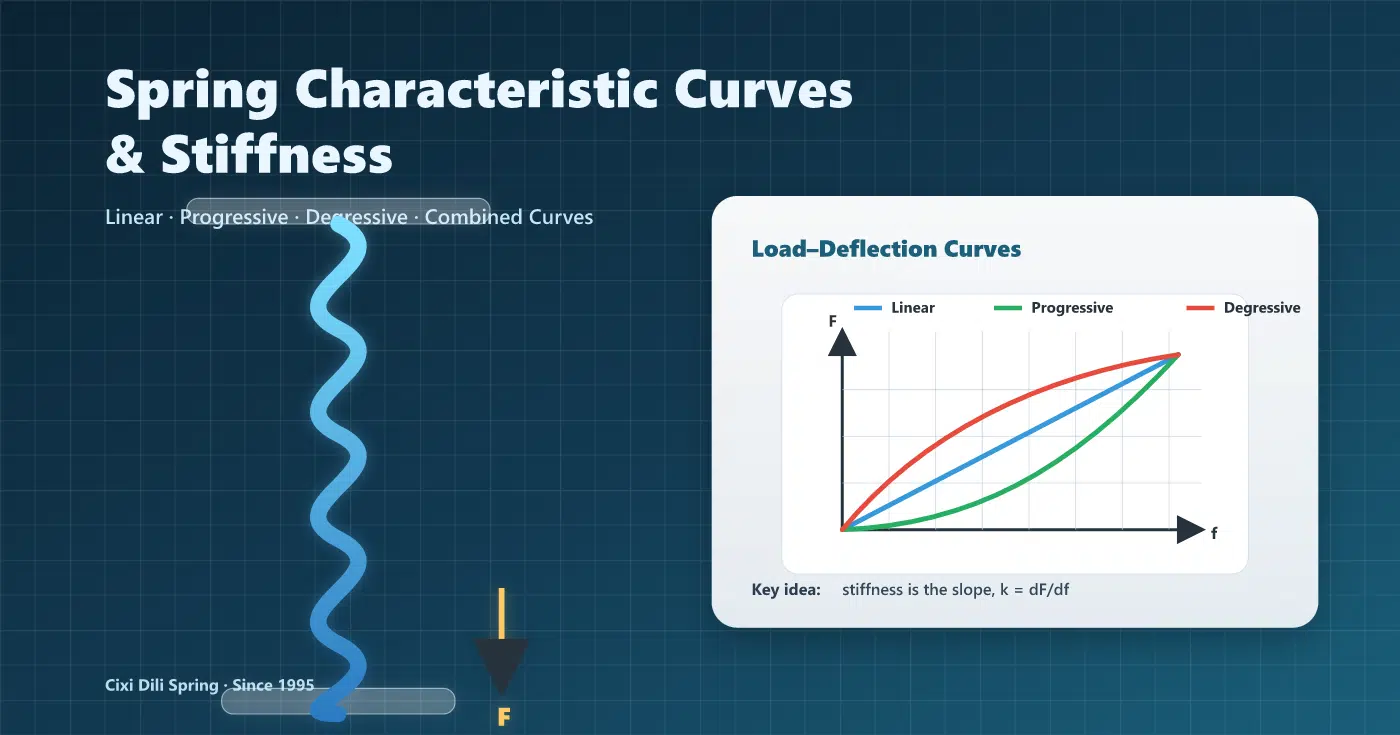
- Consistent, predictable load-deflection characteristics
- High fatigue resistance under millions of compression cycles
- Standardized dimensions enabling supplier interchangeability
- Reliable performance across different manufacturers when properly specified
Critical Engineering Truth: Different Colors Have Different Maximum Compression Limits
One of the most dangerous misconceptions in die spring selection is the belief that all JIS B5012 springs—regardless of color—share the same compression limits. This is completely false.
JIS B5012 springs are color-coded not just by load capacity, but also by maximum safe compression percentage. The heavier the load rating, the lower the maximum allowable compression.
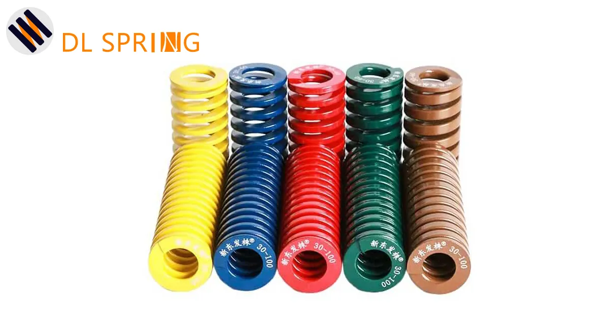
Complete JIS B5012 Color Classification with Correct Compression Data
| Series Code | Color | Load Classification | Maximum Compression | Recommended Range | Typical Applications |
|---|---|---|---|---|---|
| SF/SFR | Yellow | Extra Light Load | 50% | 40-50% (typically ≤45%) | Precision instruments, light return springs |
| SL/SLR | Blue | Light Load | 40% | 32-40% (typically ≤36%) | Small dies, ejector systems |
| SM | Red | Medium Load | 32% | 25-32% (typically ≤28%) | Standard stamping dies |
| SH | Green | Heavy Load | 24% | 19-24% (typically ≤22%) | High-force stamping, deep drawing |
| SB | Brown | Super Heavy Load | 20% | 15-20% (typically ≤18%) | Extreme force applications |
The Engineering Principle: Why Heavier Load = Lower Compression
This inverse relationship exists because:
1. Wire Thickness Increases with Load Rating
- Heavier springs use thicker rectangular wire to generate more force
- Thicker wire creates higher stress concentration at the inner coil radius
- Higher stress concentration reduces the compression distance before exceeding material fatigue limits
2. Stress Distribution Geometry
- As wire thickness increases, the ratio between inner radius and wire diameter becomes less favorable
- This geometry creates exponentially higher stress at critical points during compression
- To maintain equivalent fatigue life (1,000,000 cycles), maximum compression must be reduced
3. Material Stress Limits Are Constant
- All JIS B5012 springs use similar high-carbon chromium-silicon steel alloys
- The material’s endurance limit (stress level for infinite fatigue life) does not change
- Therefore, springs with thicker wire must be compressed less to stay within safe stress zones
Critical Takeaway:
If you need high force AND high compression stroke, you cannot simply select a heavier color. You must:
- Calculate required stroke first
- Select spring length to accommodate stroke within compression limits
- Then select color (load rating) based on required force output
Green Die Springs (Heavy Load): Specifications and Limitations
Why Choose Green (SH Series) Springs?
Green die springs represent the Heavy Load (SH) classification in the JIS B5012 standard. They deliver approximately 30-40% more force than red (medium load) springs of identical outer diameter and free length, making them essential for:
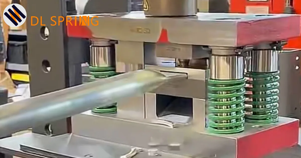
- High-tonnage stamping operations (automotive panels, appliance components)
- Deep drawing dies requiring substantial stripping force
- Injection mold ejection systems with large or complex parts
- Heavy-duty pressing equipment
- Applications where space constraints limit spring diameter but high force is required
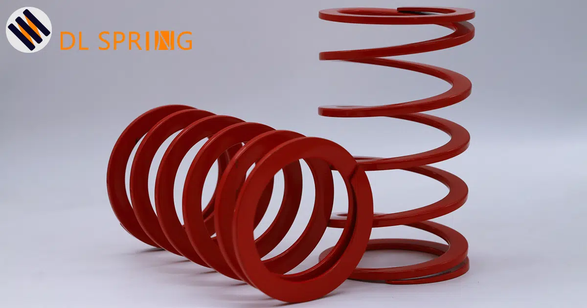
Technical Specifications of SHINDONGBAL Green Springs
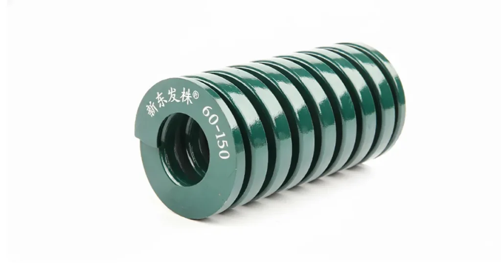
Our case study involved SHINDONGBAL 60×150 green springs manufactured by Cixi Dili Spring Co., Ltd., featuring:
- Material: 55CrSi chrome-silicon alloy steel (JIS G4801 specification)
- Heat Treatment: Oil quenching and tempering for optimal strength and toughness
- Surface Treatment: Shot peening to enhance surface fatigue resistance
- End Grinding: Both ends ground flat and parallel for uniform load distribution
- Wire Profile: Rectangular cross-section for superior stability vs. round wire
- Quality Compliance: Full adherence to JIS B5012 dimensional tolerances and performance standards
Critical Note: Even premium-quality springs from reputable manufacturers will fail prematurely when operated beyond their engineering limits.
The 24% Hard Limit for Green Springs Explained
The 24% maximum compression limit for green (SH series) springs is not arbitrary. It’s derived from extensive fatigue testing and represents the compression level where the spring can reliably achieve approximately 300,000 compression-release cycles before fatigue failure.
Compression Rate vs. Cycle Life for Green (SH) Springs:
| Compression Rate | Expected Cycle Life | Application Recommendation | Stress Level |
|---|---|---|---|
| 19.2% | 1,000,000+ cycles | Conservative / Extended Life | ~70% of material endurance limit |
| 21.6% | ~500,000 cycles | Optimal Balance | ~80% of material endurance limit |
| 24% | ~300,000 cycles | Maximum Safe Limit | ~90% of material endurance limit |
| 25.3% (Case study) | <20,000 cycles | OVERSTRESS ZONE | >100% of material endurance limit |
| >26% | Rapidly decreasing | CRITICAL FAILURE ZONE | Severe overstress – unpredictable failure |
Key Engineering Insights:
1. Exponential Relationship Between Compression and Fatigue Life
Spring fatigue life does not decrease linearly with increased compression—it decreases exponentially:
- Reducing compression from 24% to 21.6% increases life by 67% (300,000 → 500,000 cycles)
- Reducing compression from 24% to 19.2% more than triples life (300,000 → 1,000,000+ cycles)
- Increasing compression from 24% to 25.3% reduced life by 93% in our case study (300,000 → <20,000 cycles)
2. Why the 24% Limit Exists for Green Springs
At compressions beyond 24%, the stress at the inner coil radius exceeds the material’s endurance limit. The 24% limit incorporates safety margins to account for:
- Manufacturing tolerances in spring dimensions and material properties
- Installation imperfections (misalignment, non-parallel surfaces)
- Operational variables (temperature fluctuations, die wear over time)
- Load distribution irregularities in real-world applications
Exceeding 24% eliminates all safety margins and exposes your operation to unpredictable, premature failures.
Case Study: 60×150 Green Spring Premature Failure Analysis
4.1 Spring Specifications and Calculated Safe Parameters
Purchased Spring: SHINDONGBAL 60×150 JIS Green Die Spring (SH Series)
Physical Specifications:
- Series: SH (Heavy Load – Green)
- Outer Diameter: 60mm
- Inner Diameter: 30mm
- Free Length: 150mm
- Wire Cross-Section: Approximately 9mm × 12mm rectangular profile
- Material: 55CrSi Chrome-Silicon Alloy Steel (hardness HRC 48-52)
- Surface Treatment: Shot-peened and heat-treated
- End Condition: Both ends ground flat and parallel
Calculated Safe Working Parameters (Based on 24% Maximum Compression for Green Springs):
| Parameter | Calculation | Result | Expected Life |
|---|---|---|---|
| Extended Life Stroke | 150mm × 19.2% | 28.8mm maximum | 1,000,000+ cycles |
| Optimal Stroke | 150mm × 21.6% | 32.4mm maximum | ~500,000 cycles |
| Maximum Safe Stroke | 150mm × 24% | 36mm ABSOLUTE LIMIT | ~300,000 cycles |
| Overstress Zone | >24% compression | >36mm = UNSAFE | Rapidly decreasing |
4.2 Customer’s Actual Operating Conditions and Catastrophic Failure
Die Design Parameters (Customer’s Specification):
- Required Working Stroke: 38mm
- Actual Compression Rate: 38mm ÷ 150mm = 25.3%
- Exceedance Beyond Safe Limit: 38mm – 36mm = 2mm over (+5.6% beyond 24% limit)
Customer’s Pre-Production Testing:
- The customer performed bench testing of the springs before installation
- They manually compressed the springs to 42.5mm (28.3% compression)
- The springs returned to their original free length without visible damage
- Conclusion drawn by customer: “If the spring can handle 42.5mm, then using only 38mm must be completely safe”
This conclusion was fatally flawed.
Failure Timeline:
- Day 1-5: Springs appeared to function normally
- Day 6: Quality inspectors noted slight variations in part dimensions
- Day 7 (approximately 20,000 cycles): Catastrophic failure during production
Visual Evidence: Failed Springs from Customer
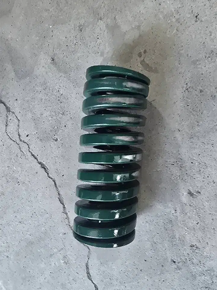
Spring #1: Complete Brittle Fracture
Failed green die spring showing classic fatigue crack propagation. The fracture occurred at mid-coil after approximately 20,000 cycles of 25.3% compression (2mm over the 36mm safe limit). Note the characteristic “beach mark” pattern indicating progressive crack growth before final sudden failure.
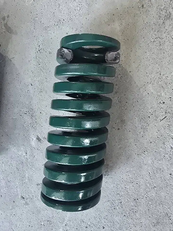
Spring #2: Severe Permanent Deformation
Second spring from the same die showing severe lateral bending and uneven coil spacing. Free height reduced from 150mm to 146mm (2.7% permanent set). This spring experienced plastic deformation from operating beyond the 24% compression limit, rendering it unable to return parts to proper position.
Detailed Failure Manifestations:
Spring #1 – Complete Fracture:
- Brittle fracture occurred at approximately mid-length of the spring
- Fracture surface analysis showed classic “beach mark” patterns characteristic of fatigue crack propagation
- Crack initiation point: inner coil radius where stress concentration is highest
- Spring fragments ejected from die, requiring complete die disassembly for removal
Spring #2 – Permanent Deformation:
- Severe lateral bending (approximately 8-10° from vertical axis)
- Coil spacing became uneven—coils compressed together on one side, spread apart on opposite side
- Free height reduced from 150mm to approximately 146mm (2.7% permanent set)
- Spring could no longer return parts to proper position, causing dimensional errors
Production Consequences:
- Immediate: 4+ hours of unplanned production downtime
- Parts: Approximately 150 rejected parts
- Labor: 2 tool makers × 4 hours at premium rates
- Replacement: Emergency overnight shipping of new springs at 3× normal cost
- Total Estimated Cost: $5,000-$7,000 for an incident that could have been prevented
4.3 Root Cause Analysis: Why 2mm Mattered So Much
Primary Cause: Operating at 25.3% compression created overstress conditions that reduced expected lifespan from 300,000 cycles to under 20,000 cycles—a 93% reduction in service life from just 2mm of excess stroke.
Mathematical Reality:
- At 36mm (24% compression): Stress ≈ 90% of material endurance limit → Safe for 300,000 cycles
- At 38mm (25.3% compression): Stress ≈ 102-105% of material endurance limit → Failure zone
4.4 Correct Solutions: What Should Have Been Done
Solution #1: Longer Green Spring of Same Load Rating (Recommended)
Specification: 60×175 green spring (SH series)
Analysis:
- Free length: 175mm
- Maximum safe stroke: 175mm × 24% = 42mm
- Customer’s required stroke: 38mm
- Actual compression rate: 38mm ÷ 175mm = 21.7%
- Expected service life: 500,000+ cycles
- Safety margin: 4mm (42mm – 38mm)
Cost Impact: Approximately $3-5 more per spring than 60×150
Benefit: 25× longer service life than the failed configuration
Customer’s Final Decision:
The customer selected Solution #1 (60×175 green springs). Post-correction results: Springs have now operated for 480,000+ cycles without failure. Total additional spring cost: ~$40. Savings vs. repeated failures: $5,000+ per failure avoided
How to Calculate Safe Working Strokes for Green Springs
5.1 The Fundamental Formula for Green (SH) Springs
Maximum Safe Stroke = Free Length × 24%
For Extended Life Applications:
• Optimal Stroke (500,000+ cycles) = Free Length × 21.6%
• Conservative Stroke (1,000,000+ cycles) = Free Length × 19.2%
Critical Reminder: These percentages apply specifically to green (SH – Heavy Load) springs. Other colors have different limits:
- Yellow: 50% maximum
- Blue: 40% maximum
- Red: 32% maximum
- Green: 24% maximum
- Brown: 20% maximum
5.2 Step-by-Step Calculation Examples
Method 1: You Have a Spring, Need to Calculate Safe Stroke
Example: 60×150 green spring
- Step 1: Free length = 150mm
- Step 2: Maximum stroke = 150mm × 0.24 = 36mm
- Step 3: Optimal = 150mm × 0.216 = 32.4mm
- Step 4: Recommended design stroke: 33-34mm maximum (leaves safety buffer)
Method 2: You Know Required Stroke, Need to Select Spring
Example: Die requires 38mm stroke
- Step 1: Minimum length = 38mm ÷ 0.24 = 158.3mm
- Step 2: Next standard length = 175mm
- Step 3: Verify: 175mm × 0.24 = 42mm ✓
- Result: 60×175 green spring is correct
5.3 Quick Reference Chart for Green Springs
| Free Length | Max Stroke (24%) | Optimal (21.6%) | Extended Life (19.2%) |
|---|---|---|---|
| 100mm | 24mm | 21.6mm | 19.2mm |
| 125mm | 30mm | 27mm | 24mm |
| 150mm | 36mm | 32.4mm | 28.8mm |
| 175mm | 42mm | 37.8mm | 33.6mm |
| 200mm | 48mm | 43.2mm | 38.4mm |
| 250mm | 60mm | 54mm | 48mm |
Common Fatal Misconceptions About Die Springs
Misconception #1: “All JIS Springs Have the Same Compression Limit”
WRONG: “All JIS springs can compress to 24%”
CORRECT: Each color has different limits: Yellow 50%, Blue 40%, Red 32%, Green 24%, Brown 20%
Misconception #2: “If I Can Compress It, It’s Safe”
Reality: Physical compression capability ≠ Cyclic compression safety
| Type | Green Spring | Application |
|---|---|---|
| Elastic Limit | 40-45% | Single cycle only |
| Safe Cyclic | 24% | 300,000+ cycles |
Misconception #3: “A Few Millimeters Won’t Matter”
- 2mm excess = 93% life reduction (case study)
- 4mm excess = 97-98% reduction
- Professional standard: ±1mm accuracy required
Installation and Maintenance Best Practices
7.1 Critical Installation Requirements
Always Use Guide Pins
- Guide pin diameter: Spring ID – 1-2mm
- Example: 60×150 spring (ID=30mm) → Use 28-29mm guide pin
- Prevents lateral deflection and buckling
Ensure Parallel Mounting Surfaces
- Flatness: ≤0.02mm
- Parallelism: ≤0.03mm
- Use counterbores for centering
7.2 Monthly Inspection Protocol
1. Stroke Verification (Most Critical)
- Use dial indicator to measure actual stroke
- Compare to design specification
- Action: If >2mm over design, stop production immediately
2. Free Height Measurement
| Height Reduction | Condition | Action |
|---|---|---|
| ≤0.5% | Normal | Continue use |
| 0.5-1% | Moderate wear | Plan replacement |
| >1% | Severe | Replace immediately |
7.3 Replacement Schedule
| Compression | Expected Life | Replace At |
|---|---|---|
| 19.2% | 1,000,000 cycles | 900,000 cycles |
| 21.6% | 500,000 cycles | 450,000 cycles |
| 24% | 300,000 cycles | 240,000-270,000 cycles |
Best Practice: Always replace complete sets, never individual springs.
Conclusion: Engineering Precision Saves Money
Key Lessons
Lesson #1: The 24% rule for green springs is absolute—it’s an engineering limit, not a guideline
Lesson #2: Different colors have different compression limits (Yellow 50%, Blue 40%, Red 32%, Green 24%, Brown 20%)
Lesson #3: Small errors = massive costs (2mm excess = 93% life reduction)
Lesson #4: Proper selection costs dollars, failures cost thousands
| Item | Incorrect (60×150) | Correct (60×175) | Difference |
|---|---|---|---|
| Spring cost | $40 | $48 | +$8 |
| Expected life | <20,000 cycles | 500,000+ cycles | 25× longer |
| Cost per 100k cycles | $13,140 | $48 | 95% savings |
| Failure cost | $5,000-7,000 | $0 | Priceless |
Die Design Checklist
- ☐ Calculate required stroke
- ☐ Verify green spring limit: 24% maximum
- ☐ Calculate minimum length: Stroke ÷ 0.24
- ☐ Round UP to next standard length
- ☐ Verify both stroke and force requirements
- ☐ Specify guide pins and mounting specs
- ☐ Establish maintenance protocol
Contact Cixi Dili Spring Co., Ltd.
Email: [email protected]
WhatsApp: +86 13586942004
We Provide:
- Free spring selection verification
- Load-deflection calculations
- SHINDONGBAL, DAYTON, DANLY, MISUMI premium brands in stock
- Custom spring manufacturing
- Technical problem-solving and failure analysis
- Same-day quotations
Engineering precision saves money.
Compression errors cost fortunes.
Frequently Asked Questions (FAQ)
Q1: Why do green springs have lower compression limits than red springs?
Answer: Green springs use thicker wire to deliver 30-40% more force. Thicker wire creates higher stress concentration, requiring lower compression to stay within fatigue limits.
| Color | Wire Thickness | Max Compression |
|---|---|---|
| Red (Medium) | Thinner | 32% |
| Green (Heavy) | Thicker | 24% |
Q2: My die needs 38mm stroke with heavy force. Which spring?
Answer:
- Minimum length = 38mm ÷ 0.24 = 158.3mm
- Select: 60×175 green spring
- Compression rate: 21.7% (safe)
- Expected life: 500,000+ cycles
Cost: $12 vs. $10, but 25× longer life = 95% lifecycle savings
Q3: Can I occasionally exceed 24% during setup?
Answer: No. Every overstress cycle adds permanent fatigue damage. Springs don’t “heal” between cycles.
Just 1% of cycles at 28% compression can reduce total spring life by 30-50%
Q4: How do I know if springs are already damaged?
Free Height Test:
| Reduction | Condition | Action |
|---|---|---|
| ≤0.5% | Normal | Continue use |
| >1% | Severe | Replace immediately |
Visual Red Flags: Cracks, uneven coils, lateral bending, blue/brown discoloration
Q5: What’s the real cost difference?
| Cost Category | Incorrect | Correct | Savings |
|---|---|---|---|
| Initial purchase | $40 | $48 | -$8 |
| Per 100k cycles | $13,140 | $48 | $13,092 |
| Per 500k cycles | $65,700 | $48 | $65,652 |
| ROI: 163,650% return on $8 investment | |||
“Saving” $8 cost $13,092 in failures—a loss ratio of 1,636:1
© 2025 Cixi Dili Spring Co., Ltd. | All technical data based on JIS B5012 standards
Email: [email protected] | WhatsApp: +86 13586942004