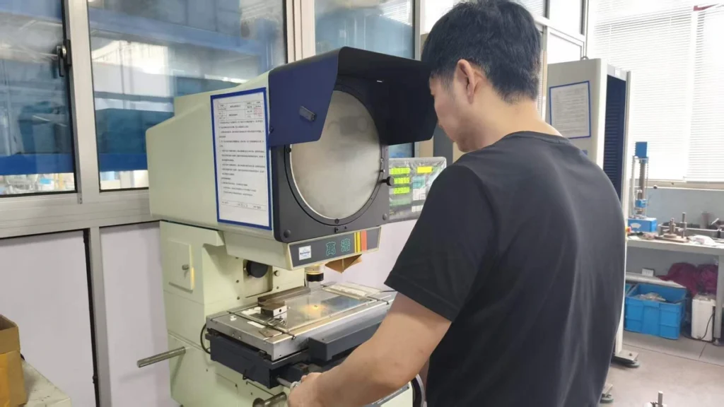
When engineering buyers, sourcing specialists, and incoming quality control personnel evaluate a supplier for custom miniature compression springs, the technical discussion frequently starts with an engineering print or a physical reference sample. Yet procurement and quality teams know that winding a small coil is only part of a successful project. The practical test of supplier coordination arrives at the receiving dock, when the buyer’s incoming inspection team evaluates the delivered parts and compares their findings against the supplier’s pre-delivery check.
With compact wire components, differences in how a spring is specified, staged, or measured can separate a smooth lot release from a time-consuming quality review. A physical sample shows that a factory can form wire into a general shape, but a sample alone rarely explains which features govern assembly function, how unloaded dimensions should be checked prior to shipment, or how the customer’s receiving laboratory should evaluate the same geometry upon arrival.
At Dingli Spring—the international brand of Cixi Dili Spring Co., Ltd.—supporting overseas engineering and sourcing teams means connecting early design clarification with practical pre-delivery verification. Dingli Spring supports spring design based on customer requirements, manufactures custom springs by drawing or sample, and checks length before delivery using an optical profile projector. This article examines the engineering and dimensional inspection questions that help buyers and suppliers establish clear, mutually useful acceptance practices from initial inquiry through incoming inspection.
Moving Beyond a Physical Sample in Custom Spring Sourcing
In international B2B manufacturing, buyers commonly open an inquiry through one of two pathways: providing a technical drawing or sending physical samples for evaluation. Dingli Spring supports both custom manufacturing from existing drawings or samples and collaborative design development based on customer needs. However, relying on an isolated sample or an incomplete sketch without technical dialogue leaves important production and inspection questions unanswered.
A physical sample represents a single piece from a prior production batch or prototype build. By itself, one piece does not indicate where it sits within the intended tolerance range, which dimensions are tightly constrained by surrounding components, or which features are secondary results of coil forming. When a buyer submits a sample without context, a manufacturer can measure that individual item, but cannot automatically see the allowable variation limits required by the end assembly. Conversely, when a drawing is submitted, it may apply generic title-block tolerances originally intended for machined metal parts rather than coiled wire geometry.
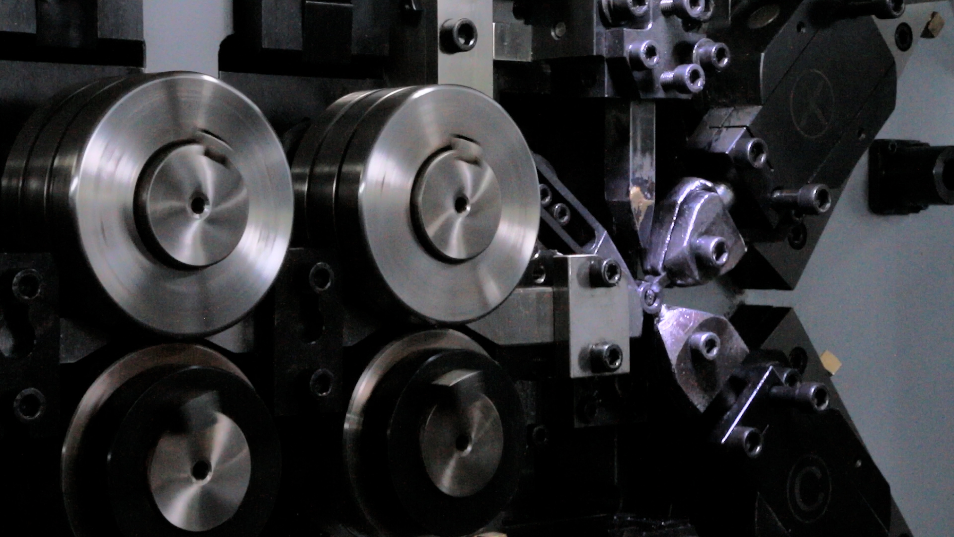
Requirement-based design support helps bridge the gap between component concept and shop-floor control. When Dingli Spring works with an engineering or sourcing team during the quotation and design stage, the goal is to translate functional expectations and spatial constraints into a manufacturable spring specification. That early conversation clarifies how the specification connects to the processo de enrolamento de mola before tooling setup begins.
For the buyer, early design review resolves practical engineering questions upfront. Which geometric characteristics control fit inside the mating mechanism? If minor coiling adjustments are required during setup, which parameters carry tight control and which allow practical manufacturing latitude? Addressing these points before production helps ensure that the parts produced on the coiling machine align with how the customer intends to inspect and assemble them.
What Buyers and Suppliers Should Establish Before Quotation and Sample Approval
Before an inquiry progresses into sample approval or serial orders for custom miniature compression springs, both the buyer’s engineering group and the supplier’s technical team benefit from agreeing on the baseline rules of specification and verification. Establishing these points early reduces commercial ambiguity and gives incoming quality personnel a clear standard for evaluating submissions.
The first recommended topic for alignment is drawing revision control and specification hierarchy. During cross-border sourcing, engineering refinements are often discussed across email exchanges while the original drawing file remains at an earlier revision. If a buyer requests an adjustment to the unloaded length or coil profile during development, both teams should confirm which document serves as the active inspection baseline. Agreeing on the governing drawing revision—or formally summarizing agreed parameters when working from a physical sample—helps ensure that outgoing checks and incoming inspections reference the exact same target.
The second area to establish is the relationship between dimensional inspection and functional testing. A complete spring requirement may include both geometric dimensions—such as spring free length and coil diameter—and mechanical behavior under load. Buyers and suppliers should clarify which characteristics are evaluated through dimensional tools and which require dedicated mechanical testing. Pre-delivery length inspection provides direct geometric evidence for the unloaded profile, whereas load testing and other functional checks require separately agreed test methods, fixtures, and deflection references.
The third area involves agreeing on the sample plan and the format of inspection evidence. Before prototype or production batches ship, sourcing teams and suppliers should discuss how many pieces will be checked, which dimensions will be recorded, and what kind of inspection documentation is useful for shipment release. Treating sampling scope and reporting format as subjects for upfront agreement ensures that factory floor checks directly support the buyer’s receiving workflow.
| Drawing or Sourcing Requirement | Recommended Supplier-Customer Method Agreement | Information Useful at Incoming Acceptance |
|---|---|---|
| Specification Baseline | Confirm the active drawing revision or agreed sample-derived parameter sheet before production setup. | A shared reference document so outgoing and incoming inspectors check parts against identical nominal values and tolerances. |
| Spring Free Length Condition | Define the unloaded resting state, support surface, and handling precautions prior to dimensional evaluation. | Consistent staging conditions that help distinguish true part geometry from handling or support distortion. |
| Measurement Axis & End References | Specify how the longitudinal axis is aligned and which terminal features on both ends define the overall length boundaries. | Clear datum definitions that allow both labs to sight the same end boundaries along the same measurement direction. |
| Inspection Method Selection | Select optical profile projection or qualified contact gauges suited to the spring’s stiffness, and separate load testing into its own procedure. | Clarity on the equipment type used for length checks versus the methods used for force or functional verification. |
| Sampling & Evidence Format | Agree on the sample size, recorded dimensional values, and report layout expected with prototypes or shipments. | Structured dimensional records that incoming quality personnel can review and compare against their own check results. |
Why Unloaded Free Length Needs Clear Measurement Conditions
Among the dimensions specified on a compression spring drawing, spring free length—the overall axial length of the spring when no external load is applied—is a primary checkpoint for both setup verification and incoming quality control. On a print, free length appears straightforward: two parallel extension lines marking the ends of the coil with a target dimension and tolerance. In practice, measuring the unloaded length of a miniature spring requires attention to how the part responds to physical contact and how it sits during inspection.
Whether a traditional contact tool—such as a caliper, micrometer, or indicator gauge—affects a free-length reading depends on the stiffness of the specific spring and the gauging technique used. Not every miniature spring is delicate; stiffer small coils can be measured reliably with qualified contact methods when the gauge force and operator technique are appropriate for the part’s spring rate and tolerance. However, when a miniature compression spring has a low stiffness rate or fine wire geometry, closing contact measuring jaws against the ends of the coil can introduce axial pressure that slightly deflects the spring or tilts it between the measuring faces.
Axial measuring force can deflect a spring enough to affect the reported dimension relative to its tolerance. Differences in operator pressure may therefore change a reading. A suitable method should control or account for contact-force effects instead of assuming that a light touch always leaves the free length unchanged.
Beyond gauge pressure, the physical condition and staging of the spring must be defined. Parts should be separated carefully before inspection so they are not entangled or pre-stressed from bulk handling. The surface supporting the spring must be clean and flat, and both teams need a shared understanding of how the longitudinal axis and terminal ends are referenced. If your team is reviewing measurement conditions for a new component, exploring Dingli Spring’s custom springs manufacturing solutions offers a direct path to align design specifications with practical shop-floor verification.
Optical Length Inspection and Profile Alignment for Miniature Springs
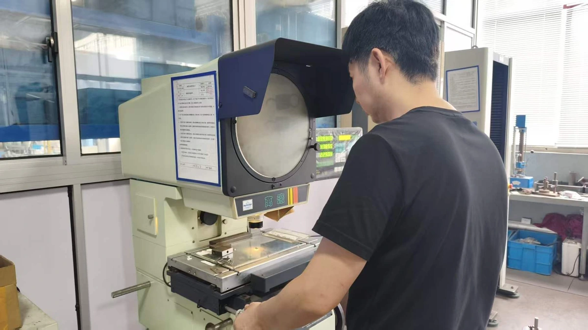
To check the length of small springs before delivery without applying axial jaw pressure against the coil ends, Dingli Spring uses optical length inspection on an optical measuring and profile projector. An optical profile projector—also known as an optical comparator—illuminates a component placed on a glass stage and projects a magnified shadow profile onto a viewing screen equipped with reference lines and stage coordinate tracking.
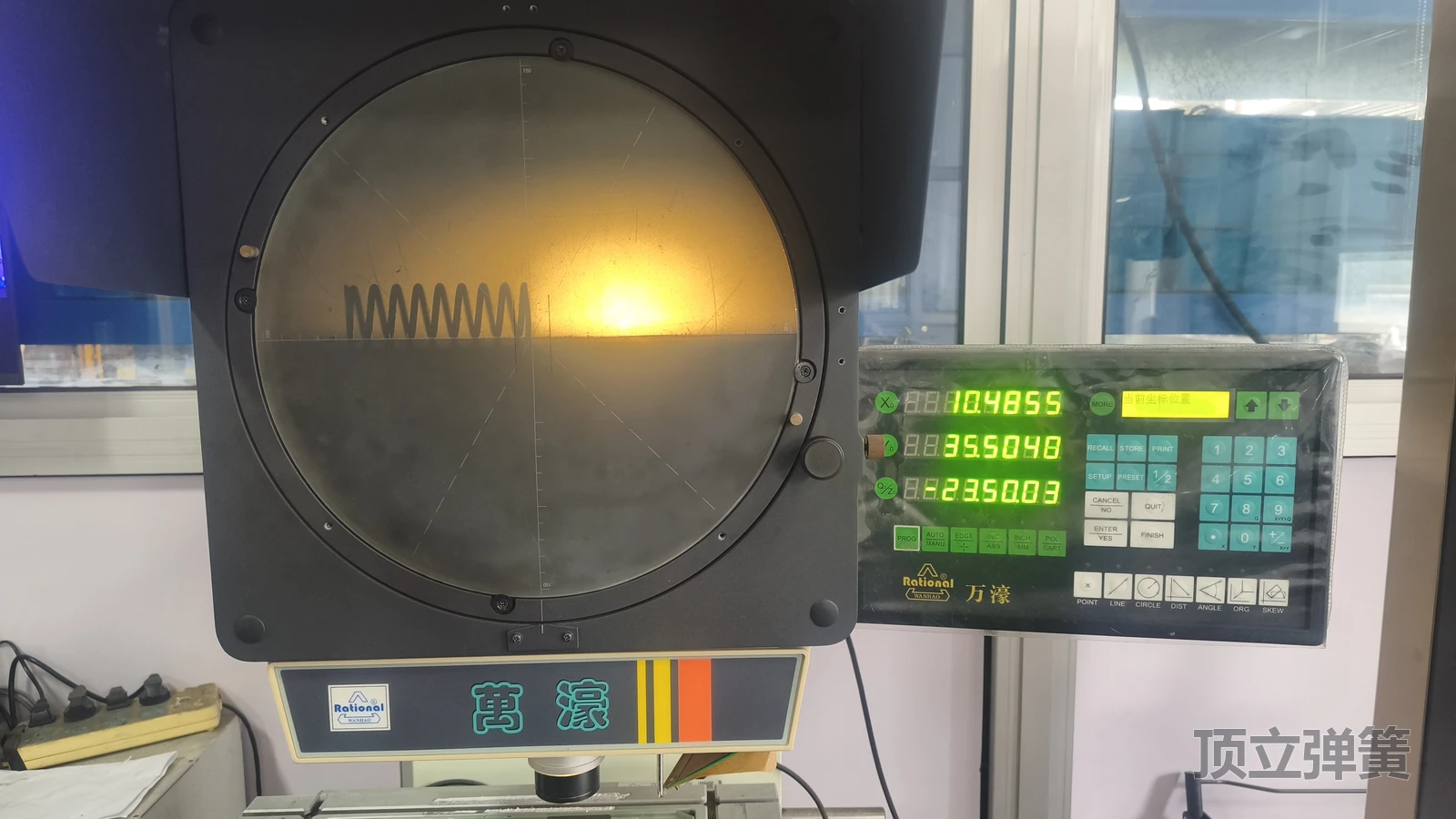
The photograph shows a small compression-spring profile on the optical projector screen at Dingli Spring. It illustrates the projected silhouette and measurement references. For compression-spring length checks, optical observation helps locate the defined end boundaries without axial measuring-jaw pressure. Reliable results still depend on suitable support, alignment, focus, and measurement references.
First, physical support and stage cleanliness directly affect the projected profile. The spring rests on the stage surface under gravity, so the glass must be clean and free of debris or fluid film that could tilt the part or blur the shadow boundary. If a spring is placed unevenly or rests on a foreign particle, the projected length along the viewing plane can be foreshortened by tilt relative to the stage.
Second, optical focus must be adjusted carefully for the plane being observed. On round wire coils, shifting the focal plane changes the sharpness of the projected silhouette edge. Establishing crisp focus before sighting the endpoints helps ensure that the inspector aligns the screen reference line with the true profile boundary rather than a diffused shadow edge.
Third, defining the measurement axis and the two end references is essential. A spring’s true overall axial free length does not change simply because an unchanged part rests in a different rotational orientation around its own longitudinal axis. However, in practical inspection, if an operator sights an arbitrary local feature on one coil end rather than the overall axial envelope, or if the spring tilts differently on the stage, or if part of an end contour is occluded or out of focus, the observed reading can vary. Similarly, if the terminal ends contain cutoff features, burrs, or geometric irregularities, inspectors must not ignore nonconformities or cherry-pick a convenient point just to obtain a passing number. The drawing or agreed inspection method must clearly define whether the measurement references the overall axial envelope between the outermost terminal points parallel to the spring’s central axis, and parts must conform to all agreed end-finish requirements.
Interpreting Coordinate Readings and Recording Inspection Results
When quality teams discuss profile projector checks or review equipment displays, understanding how coordinate measurements work—and what metrology terminology actually means—helps keep spring acceptance criteria grounded in sound engineering practice.
On an optical profile projector equipped with a digital readout, a single coordinate value visible on the display at a static moment is not a complete length result on its own. Optical coordinate length measurement determines the distance between two defined end references along a specified measurement axis. In practice, once the spring’s longitudinal axis is aligned with the stage travel direction, the first terminal reference point is sighted at the crosshair (establishing the starting datum or zero reference), the stage is translated parallel to the measurement axis until the crosshair sights the opposite terminal reference point, and the coordinate difference between those two aligned positions represents the measured length.
Display resolution describes the readout’s indication granularity. Measurement accuracy concerns how close a result is to the actual dimension being measured. Fine display increments do not by themselves establish accuracy or measurement uncertainty.
A fine readout increment on a digital screen does not by itself define the overall accuracy or uncertainty of the inspection. Actual measurement performance depends on the verified condition of the equipment, stage scale performance, optical magnification and focus, lighting contrast, part staging stability, and the consistency of the operator’s procedure. Rather than treating a display increment as a standalone capability statement, buyers and suppliers can discuss what level of dimensional verification and recorded evidence is appropriate for the specific part and tolerance.
Technical references: Mitutoyo’s explanation of non-contact profile projection; JCGM VIM measurement accuracy e resolution of a displaying device. These explain general principles and terminology, rather than the capabilities of the photographed equipment.
Aligning Outgoing Checks with Customer Incoming Inspection
When a supplier conducts pre-delivery length checks and a customer performs incoming quality inspection upon receipt, strong correlation between the two labs keeps supply chains moving efficiently. If an outgoing check and an incoming check produce different length numbers on a batch of custom miniature compression springs, quality teams should avoid jumping to one-sided conclusions. A difference between two inspection reports is not automatically a measurement artifact, nor is it automatically proof of faulty coiling; it can reflect a real part difference within or across the lot, a physical change caused by packaging or transit handling, a setup issue at either facility, or a difference in measurement methods.
To prevent avoidable discrepancies and investigate any differences systematically, engineering buyers and incoming quality teams can align with their supplier across five practical areas:
- Reviewing Both the Physical Parts and the Measurement Setup: When outgoing and incoming numbers diverge, start by examining the physical springs for transit tangling, deformation, or end-coil irregularities alongside a review of how both labs staged and measured the samples. Checking both the hardware and the procedure ensures real dimensional issues are caught while method differences are clarified.
- Matching Gauge Principles to Spring Stiffness: Coordinate on whether free length will be inspected by optical profile projection, vision systems, or qualified contact gauges. When low-stiffness miniature springs are involved, aligning both outgoing and incoming checks on non-contact optical observation avoids disagreements caused by caliper jaw pressure on one side of the supply chain.
- Defining Axis Alignment and End Datums: Agree explicitly on how the spring’s longitudinal axis is referenced on the inspection stage and how the terminal endpoints are sighted. Confirming that both labs measure the overall axial distance between defined end boundaries parallel to the central axis reduces directional cosine errors and sighting ambiguity.
- Controlling Stage Support and Focus: Ensure both inspection stations place the cleaned spring on a flat, unobstructed reference surface with crisp optical focus on the terminal wire contour. Consistent staging prevents slight part tilt or shadow blur from skewing recorded values.
- Separating Dimensional Checks from Other Acceptance Criteria: Optical length inspection supplies dimensional evidence for the unloaded profile. Load at specified heights, coil diameters, end squareness, or material and surface checks should each follow their own agreed inspection methods and acceptance rules so every requirement is verified by an appropriate tool.
Frequently Asked Questions About Optical Spring Inspection
What does optical length inspection verify on custom miniature compression springs?
Optical length inspection provides dimensional evidence for the unloaded length of the spring—commonly called spring free length—by projecting a magnified silhouette of the part onto a screen for coordinate measurement. Observing the profile optically avoids applying axial measuring-jaw pressure against the ends of the coil during the length check. While it verifies the unloaded length geometry under the defined staging condition, load testing and other functional performance characteristics require their own separately agreed testing methods.
How should supplier and customer teams define spring endpoints during measurement?
The drawing or agreed inspection procedure should specify the measurement axis parallel to the longitudinal center of the spring and define the exact terminal features on both ends that form the length boundaries. Typically, this means sighting the outermost axial points of the overall profile envelope along the defined axis rather than picking arbitrary local points, while also verifying that end finishes and cutoff features meet the specification without burrs or nonconformities.
What is the difference between display resolution and measurement accuracy on a profile projector?
Display resolution concerns the readout’s indication increments; accuracy concerns agreement with the actual dimension. Overall measurement performance depends on the equipment and method, including focus, alignment, support and endpoint selection. Decimal places alone do not establish that performance.
How should teams handle differences between supplier outgoing readings and customer incoming checks?
Teams should evaluate both the physical parts and the inspection procedures used at each location. A discrepancy may stem from actual part-to-part variation, deformation or tangling during packaging and shipping, stage tilt or focus differences, or one lab using contact calipers while the other uses optical projection. Reviewing physical sample condition alongside axis alignment, endpoint datum rules, and gauge type helps identify whether the root cause lies in the product, transit handling, or the measurement method.
How can engineering and sourcing teams start a design and inspection discussion with Dingli Spring?
Buyers can reach out with their technical drawings, functional requirements, or physical samples, along with notes on which dimensions and acceptance checks are priority items for incoming inspection. Dingli Spring works with customers to support requirement-based spring design, manufacture custom springs by drawing or sample, and align on practical pre-delivery optical length inspection so outgoing checks support a smooth incoming acceptance process.
Work with Dingli Spring on Your Next Custom Spring Project
Sourcing custom miniature compression springs is far more predictable when component design, manufacturing capability, and dimensional inspection criteria are aligned early. At Dingli Spring (Cixi Dili Spring Co., Ltd.), we support spring design based on customer requirements, provide custom manufacturing by drawing or sample, and perform pre-delivery length checks using an optical profile projector to supply clear dimensional evidence before shipment.
Whether you are developing a new miniature compression spring specification, qualifying a custom supplier for an existing drawing, or coordinating incoming inspection methods with your quality team, we are ready to review your project requirements in confidence.
To discuss your drawing, sample, or dimensional inspection needs, visit our página de contato or contact our team directly:
- Company: Dingli Spring (Cixi Dili Spring Co., Ltd.)
- E-mail: [email protected]
- WhatsApp: +86 13586942004